


Mastering the M4 Scene Operational Interface: Understand Robots, Transport Orders, and On-Site Status at a Glance
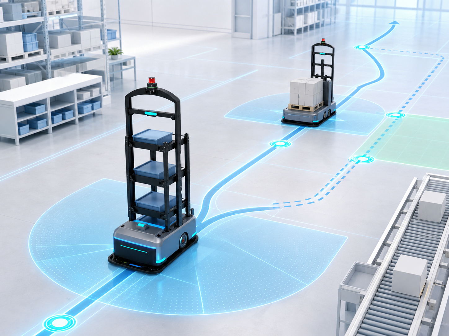
As the fleet size grows, on-site management needs to answer several key questions simultaneously: Where are the robots? What transport orders are they executing? Where are they heading next? And why are they waiting?
The M4 scene operational interface consolidates the scene map, robots, transport orders, and dispatching status into a single view. A single M4 system can run multiple scenes, and each scene can contain different zones. By switching “scenes” or “zones” on the M4 “Dispatching Scene” page, users can immediately view the corresponding site conditions.
Quickly Identify Specific Issues from Global Overview
Key metrics regarding robots, transport orders, and system status are summarized at the top of the interface. Clicking on a specific status count directly filters the corresponding objects; combined with search and element locating functions, users can quickly narrow down the troubleshooting scope from a high-level overview.

The robot list and transport order list maintain real-time synchronization with the map. Selecting a robot displays its current location, operational status, assigned transport order, and other relevant details. Selecting a transport order allows users to verify the assigned robot, target point, and task progress. Clicking on points, paths, or equipment on the map brings up the details panel on the right, displaying the properties and status of the selected object.
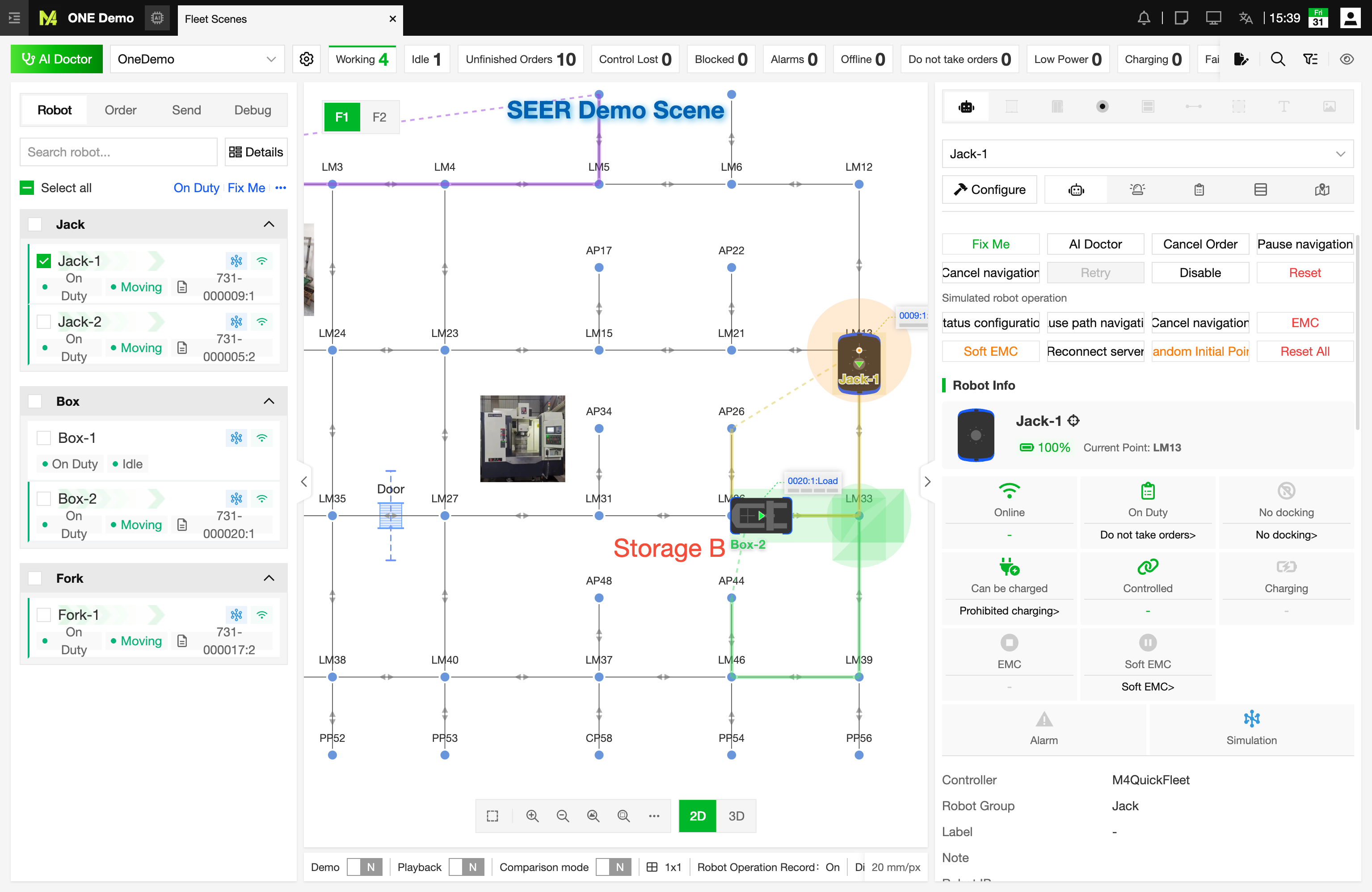
In this way, users can quickly assess on-site operations following a clear logic: check for statistical anomalies first, locate the specific robot or transport order next, and finally evaluate site conditions using the map and detail panels.
Display Settings Adapt a Single Map to Diverse Viewing Needs
While on-site robotic operations generate vast amounts of data, user focus varies depending on the task. During routine inspections, monitoring robot names and operational status might suffice. However, troubleshooting traffic control issues requires observing target points, planned paths, and reserved spatial resources simultaneously.
M4's Display Settings allow users to customize what information appears on the map and how it is rendered. Users can switch between robot icons and collision models, adjust transparency, toggle name and status cards, or selectively render map elements such as points, paths, racks, and point clouds as needed.
When a scene is running, the following three elements are most critical for understanding a robot's next actions:
- Robot Target Point: Typically indicated by a dashed line pointing to the robot's current target destination. Since a transport order may consist of multiple actions, this displays the navigation target for the current step.
- Planned Path: Highlighted with thick lines in different colors to show the real-time future paths calculated by the dispatching system for each robot. Trajectories of different colors may intersect or overlap.
- Spatial Resource Occupancy: Represented by combinations of rectangles or fan shapes of the same color, showing spatial resources already occupied by or allocated to a robot. A single color corresponds to the spatial resources reserved by one robot; spatial resources of different colors never overlap. These resources are utilized for collision detection and traffic management, helping users determine why a robot is waiting, yielding, or held back from entering a specific area.
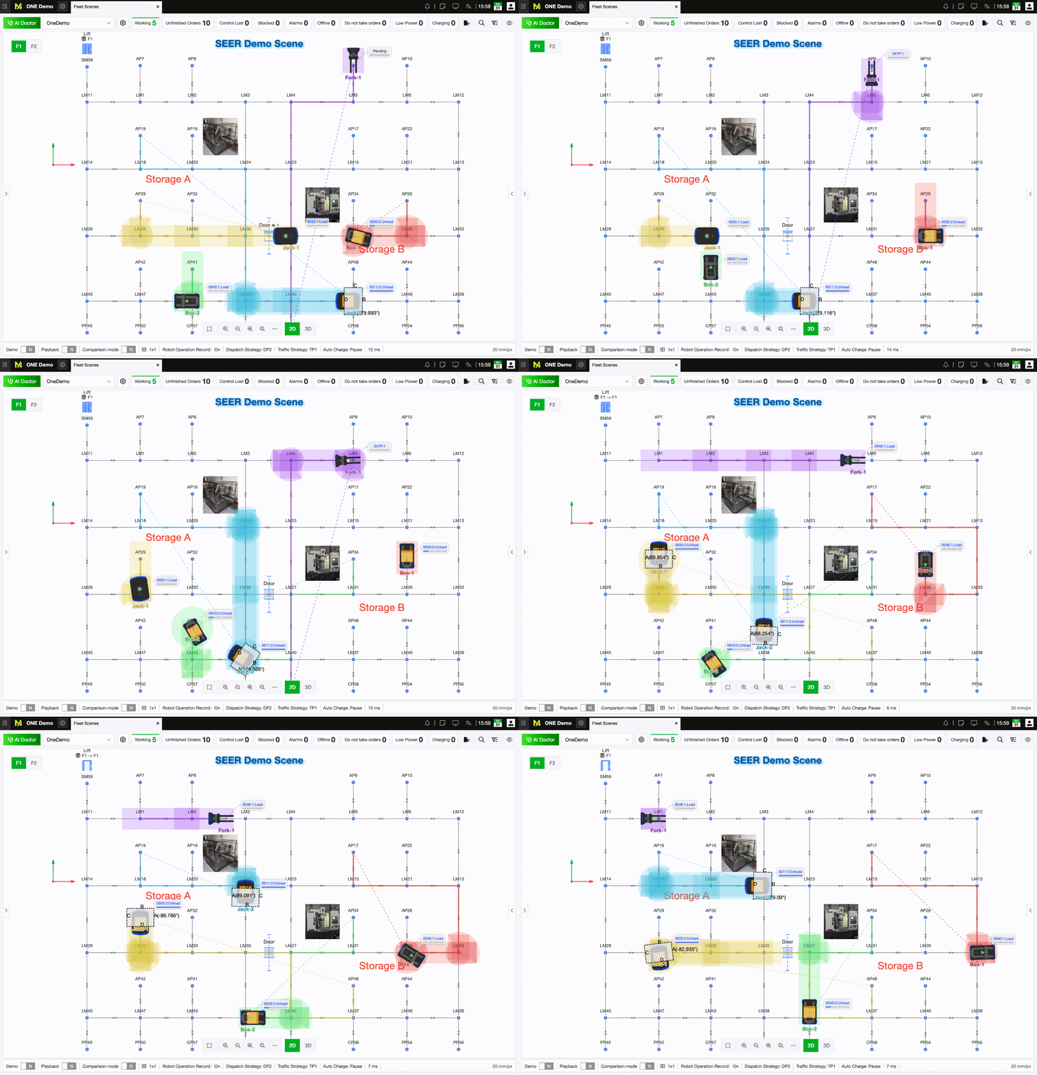
Combined, these three elements answer “Where to go,” “How to get there,” and “Is this space available?” respectively. When a robot stops unexpectedly or takes a detour on-site, users can first verify if the target point is correct, then check for conflicts between planned paths and spatial resources.
For large-scale maps featuring high densities of robots and points, users can enable Large Scene Mode. This mode uses fixed yet adjustable robot icon sizes and highlights robot status. Details like names, status cards, planned paths, and spatial resources are hidden by default and only pop up when a robot is selected, during which its target point line also changes from gray to the robot's corresponding color. This enables users to monitor overall operations before zooming in on abnormal or priority vehicles, significantly reducing visual clutter caused by overlapping labels and routes.
Presentation Mode, Compare Mode, and Split Screens for Complex Sites
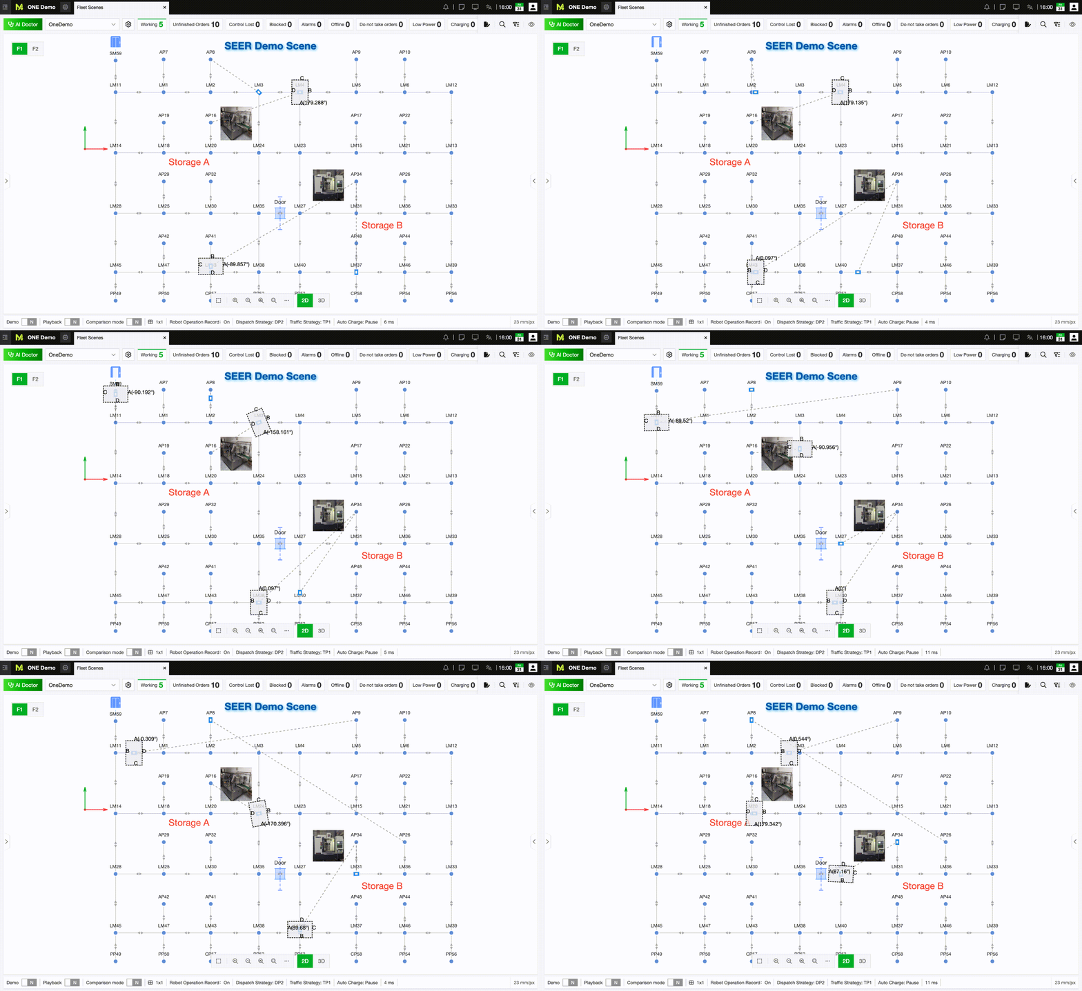
During client visits, exhibition center displays, or unattended demonstrations, overview maps might fail to showcase robot details clearly, while fixed local views risk showing empty areas for long periods. In such cases, Presentation Mode can be activated. The map view automatically cycles through and focuses on active robots, providing audiences with continuous close-ups of live operations without manual adjustments.

When multiple target robots require simultaneous tracking, Compare Mode highlights selected objects while minimizing visual noise from surrounding elements.
Once Compare Mode is active, all robots on the map are unified in gray, while selected robots are highlighted alongside their target points, planned paths, and spatial resources. Even in high-density operations with overlapping routes, users can swiftly distinguish key robots, observe their dynamic interactions, or troubleshoot anomalies.
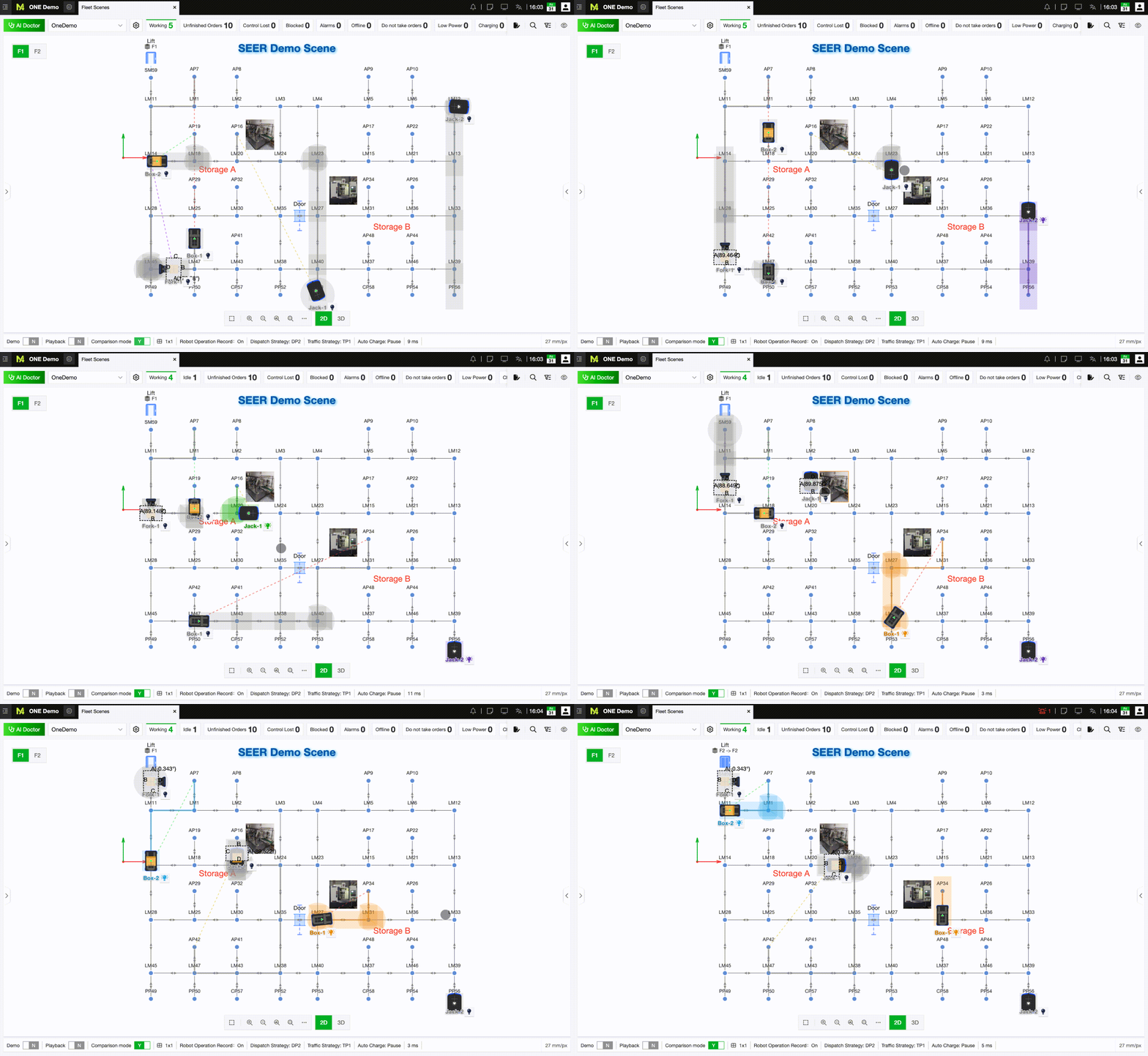
For cross-zone or multi-floor sites, Map Split Screen allows side-by-side observation of different areas within a single view.
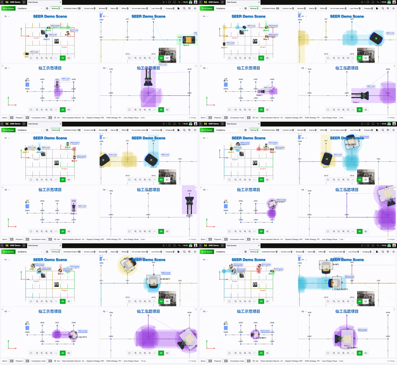
Map Split Screen supports customizable rows and columns, displaying up to 9 viewports simultaneously. For instance, in a 2 × 2 grid: the top-left and bottom-left panes can display the macro scene maps for the 1st and 2nd floors respectively, while the top-right and bottom-right panes show localized operational scenes for each floor. This layout provides both high-level visibility across floors and detailed tracking around critical workstations, narrow aisles, or equipment.
The Scene Status Bar at the bottom of the interface consolidates runtime logs, dispatching policies, traffic policies, and communication latency. It serves to both confirm whether the current scene is configured as intended and provide essential operational context for troubleshooting.
Operational Logs Enable Issue Reproduction
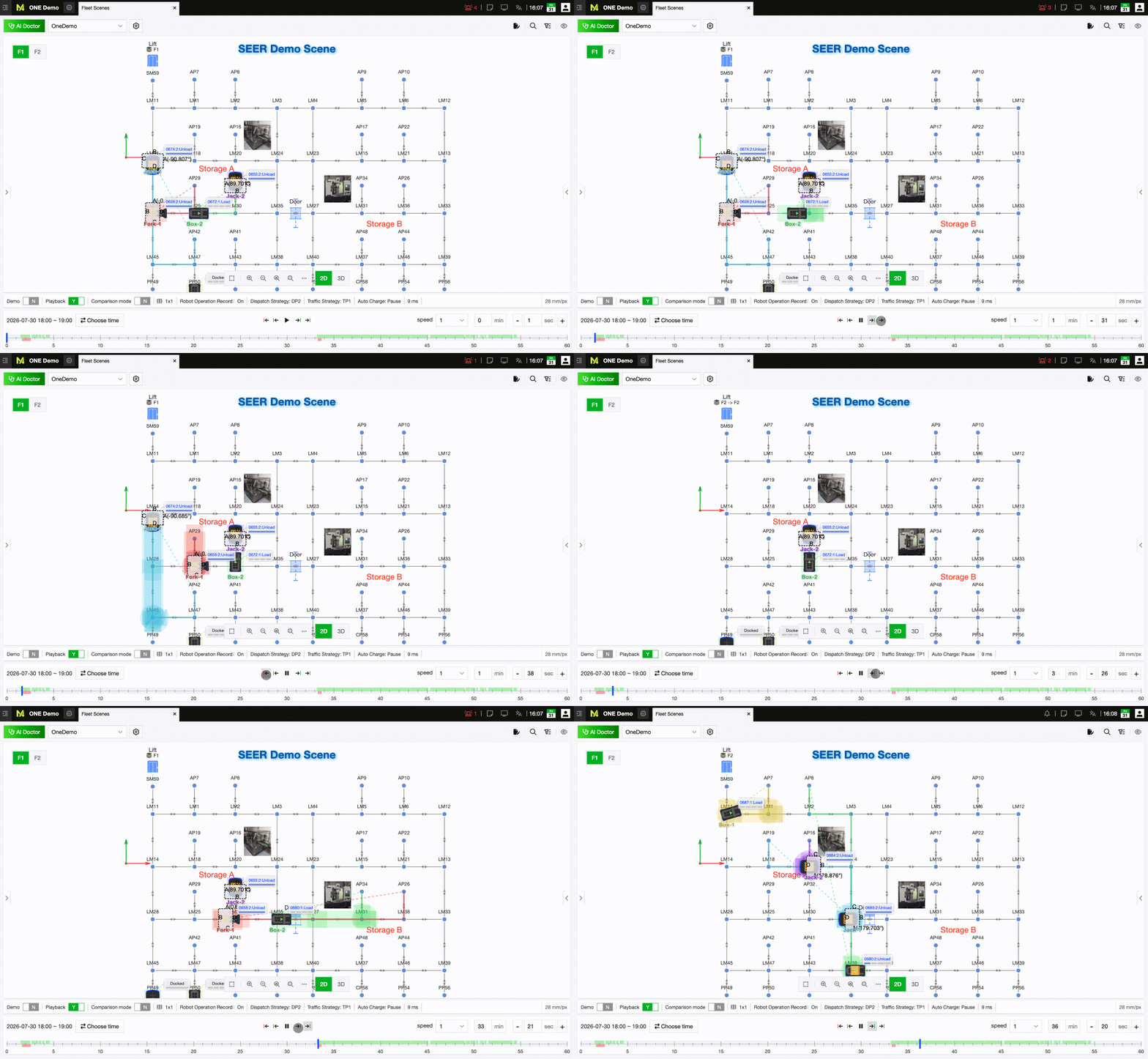
For intermittent delays, route anomalies, or execution issues with transport orders, live screenshots often capture only a single static frame. By enabling Operational Logs, users can replay historical robot statuses, transport order updates, and map information step-by-step—reconstructing the dispatching logic along target points, planned paths, and spatial resources.
The playback feature also includes convenient skip options: “Previous/Next Error Log” and “Previous/Next Normal Log.” This helps users bypass irrelevant intervals and quickly inspect site conditions before and after status changes.
Scene Operations: Bringing Clarity to Site Conditions
The core value of the scene operational interface lies in transforming fragmented site data into a clear diagnostic workflow: spot anomalies via the status overview, pinpoint targets via robot and transport order lists, and analyze dispatching behavior using the map and display settings. Routine inspections, on-site collaboration, and issue post-mortems can all be seamlessly conducted within a single interface.
