


M4 Scene Map: The Basis for Where, How, and Whether Robots Can Move

In M4, a scene map serves as an on-site manual for the dispatching system. It translates floors, workshops, aisles, workstations, and storage locations into points, paths, and operational rules that robots can recognize.
Its hierarchy within M4 can be summarized as follows:
Project → M4 Dispatching System → Scene → Region → Robot Group Map → Map Elements
A scene defines a self-contained dispatching environment, regions correspond to specific physical spaces, and robot group maps specify how particular types of robots operate within a region. Where a robot goes, which path it takes, and whether it is permitted to enter a target region are all determined based on the map.
Scene Maps Enable M4 to Understand the Site
When a business system issues a request such as “deliver a pallet from the 1st-floor warehouse to the 2nd-floor production line,” M4 first identifies the pickup and target points, determines which robots are eligible to enter the relevant regions, and then selects a viable route along with the necessary elevators.
All of these decisions rely on the map. Missing maps or incorrect spatial relationships can result in failed task assignments, routing errors, or robots being unable to reach their destinations.
Regions and Robot Groups Define Robot Operational Boundaries
A single M4 system can manage one or multiple scenes. A scene can be divided into multiple regions by floor or workshop. Robots can operate across different regions within the same scene, but they will never execute tasks across different scenes.
Because different robot types vary in size, turning mechanisms, and load handling positions, maps must be mapped to specific robot groups:
Region × Robot Group = Grouped Map
M4 displays a merged view of the maps for all robot groups within the same region while preserving the unique attributes of each group. For example, a point can be configured to allow latent lifter AGVs to park while prohibiting forklifts; if the 2nd floor only has a map for the latent lifter group, M4 will not assign 2nd-floor tasks to forklifts.
Multiple grouped maps within the same region must also share a consistent coordinate origin and orientation to prevent spatial offsets for the same location across different robot types.
Points, Paths, and Storage Locations Guide Robot Actions
An M4 scene map primarily consists of the following elements:
- Points: Locations where robots pass through, park, or execute actions. Common types include Location Points (LM), Action Points (AP), Parking Points (PP), Charging Points (CP), and Switch Map Points (SM).
- Paths: Directed lines connecting points. Lines with a single required direction are unidirectional paths with defined start and end points. Lines where either connected point can serve as the start or end point are bidirectional paths.
- Storage Locations: Locations designated for cargo storage, typically linked to AP points. A single point can be associated with multiple storage locations, and storage locations can be configured with BinTasks. BinTasks trigger specific actions for the robot to perform. When placing an order, specifying a storage location allows the robot to locate the associated point and navigate to it automatically.
- Zones, Text, Images, and Environment Point Clouds: Used to render site boundaries, backgrounds, and spatial references.
Selecting a point opens the right-hand property panel, where its operational parameters can be fine-tuned.
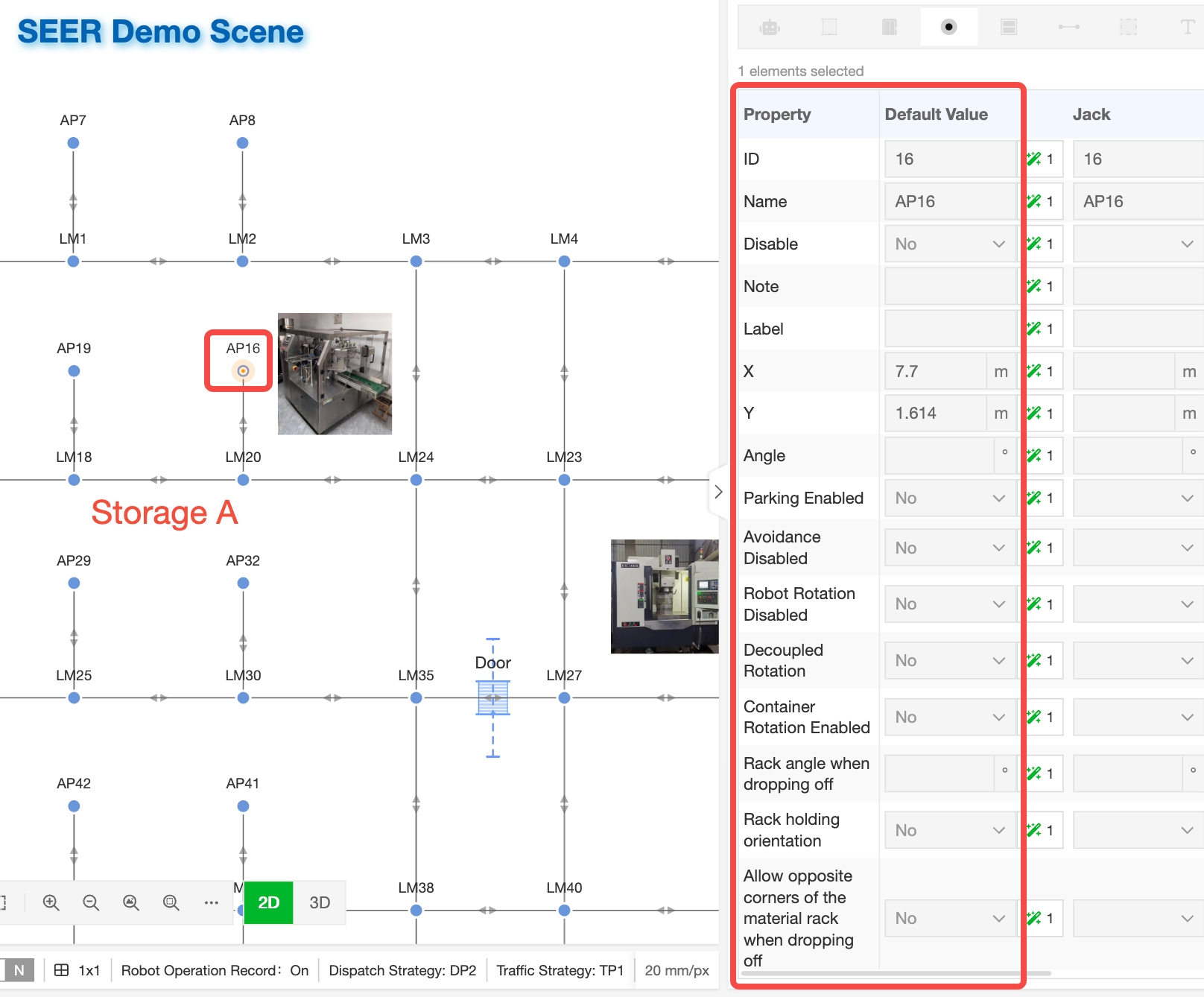
IDs, names, tags, remarks, and disabled statuses are used to identify and manage points, while X/Y coordinates and angles determine their physical position and heading on the map. Toggles such as Allow Parking, No Detour, No Rotation, Follow-along, and Direction Change Point constrain robot behavior when reaching or traversing a point. For points requiring rack handling, you can configure the rack drop-off angle, choose whether to maintain heading, and enable diagonal docking. When necessary, robots can also request resources for connected paths simultaneously to minimize traffic conflicts when entering or exiting a point.
These properties support both “Default Values” and “Robot Group-Specific Values”. Common rules can be configured globally, while unique requirements for specific robot types can be adjusted individually within their respective robot groups. This minimizes duplicate configurations while preserving operational differences across robot types.
Viewing and Editing Maps Directly within a Dispatching Scene
When a scene contains multiple regions, users can switch views between different floors or workshops, adjusting the viewport by dragging, zooming, fitting to view (“Show Full Map”), or box-zooming. The search feature enables quick localization of robots, points, and storage locations. Selecting a map element displays its detailed properties and group-specific attributes in the right panel.
After selecting a region, click the Edit button in the top right corner to modify the map. Once in edit mode, the scene selector locks to prevent users from accidentally switching scenes during editing. Remaining in view mode by default reduces the risk of accidental map changes during live site monitoring.
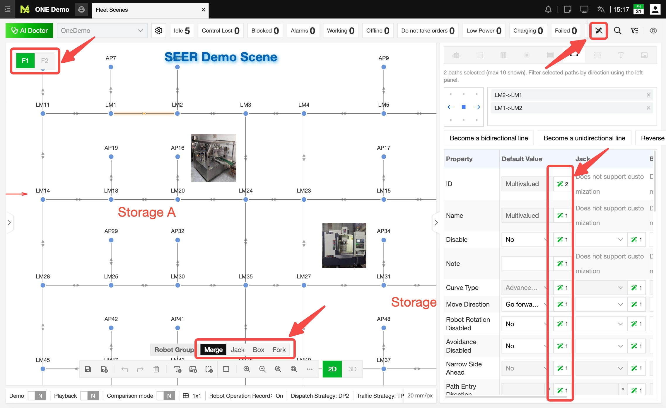
The editing interface provides access to a “Merged View” as well as individual robot groups. The “Merged View” is used to configure shared defaults, while groups like Jack, Box, and Fork retain their own traffic and parking attributes. In this way, common configurations do not require redundant maintenance, and robot-specific differences will not be overwritten.
The bottom editing toolbar places frequently used actions right next to the map. Save and Cancel confirm or discard the current changes, while Undo and Redo allow quick corrections. Delete, Text, Image, and Zone tools help organize the map and supplement site context. Box Select, Zoom In, Zoom Out, Show Full Map, and Box Zoom make handling large-scale maps effortless.
After saving a map, users can choose between “Push Later” or “Push Now”. Choosing “Push Now” uploads the updated map directly to the corresponding robots. Choosing “Push Later” saves the changes locally within the system, allowing manual deployment at a scheduled time. Decoupling system configuration saves from active robot map updates allows for thorough verification before deployment, minimizing disruptions to live plant operations.
Accurate Maps Reduce Operational and Expansion Costs
A reliable scene map requires that points and storage locations match physical positions, paths adhere to real-world traffic conditions, robot groups correctly align with regions, and all grouped maps remain perfectly calibrated. Outdated maps can lead to task assignment failures, routing issues, robot bottlenecks, and increased manual interventions.
When expanding a project, the map architecture offers a clear path for scalability: to add a floor, create a region and its corresponding robot group maps; to add a new robot type, create a robot group and configure its authorized operating regions.
While robots determine who executes the job and transport orders specify what needs to be done, scene maps instruct M4 on where to do it, how to get there, and which robots are allowed to go. It is the foundation for M4 to comprehend physical sites and orchestrate fleet operations.
