


LP1 & LP2 — Two Elevator Scheduling Modes for M4
Why Elevator Scheduling Requires Two Modes
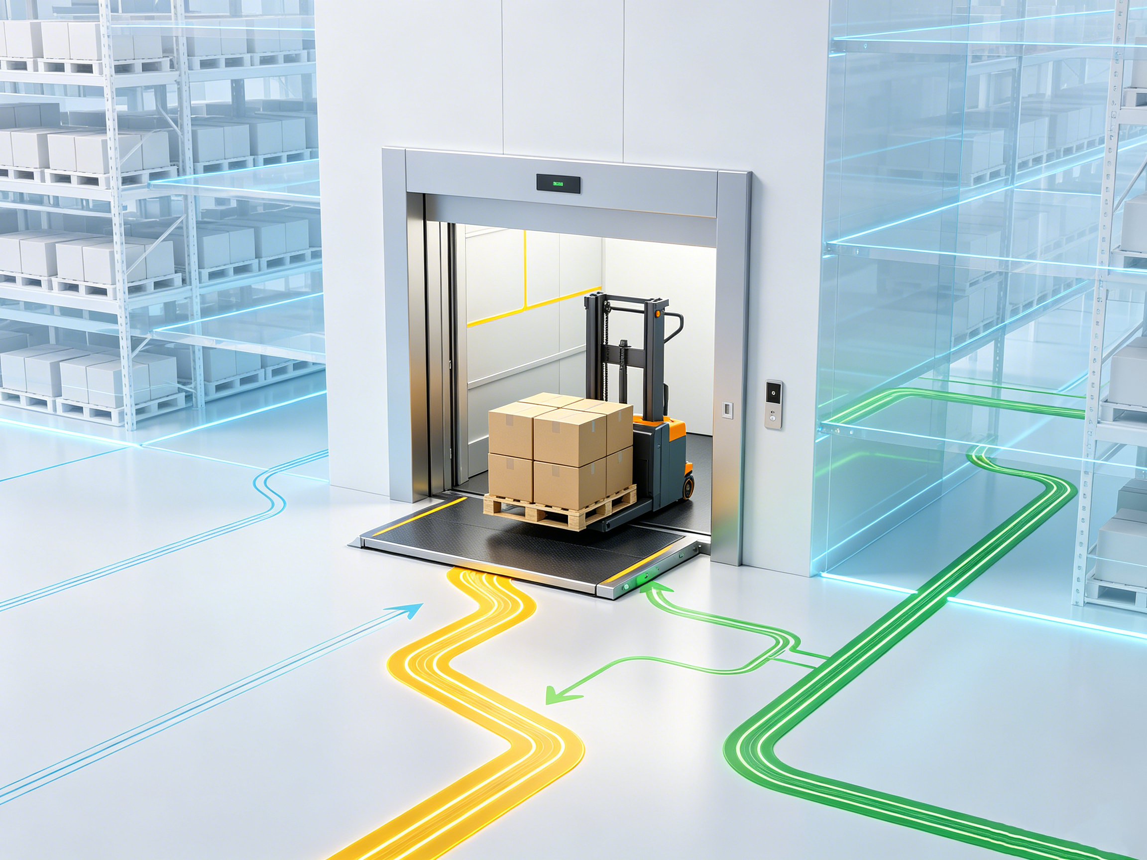
In multi-floor warehousing and production scenarios, elevators are critical bottlenecks for robots operating across floors. When there are only a few robots on-site and elevator resources are relatively abundant, a simple "occupy-on-demand and release-after-use" logic works perfectly. However, as operations scale up and robot density increases, the "one robot at a time" approach quickly becomes a major throughput bottleneck.
The M4 currently supports two elevator scheduling modes: LP1 and LP2. These two solutions are designed for different site conditions.
- Configuration Path: Scene Edit → Elevator → Scheduling Mode.
LP1 Mode: Exclusive Elevator Usage
LP1 is the earliest elevator scheduling mode supported by M4, utilizing the Timeline algorithm at its core. The core rule is straightforward: only one robot is allowed to enter a specific elevator at any given time. The elevator resource is only released after the robot completes the entire riding process and reaches the designated post-position node.
1. Applicable Scenarios
LP1 is the recommended option for sites that do not require multi-robot co-riding, or where there are sufficient elevators so that queuing does not impact overall efficiency. LP1 features a low configuration threshold, simple mapping requirements, and intuitive operations and maintenance (O&M).
2. Queue Capacity at Elevator Entrances
LP1 allows users to configure the maximum number of robots permitted to wait at each elevator entrance.
- Configuration Path: Scheduling Scene Edit → Configuration → Elevator.
- Purpose: This setting helps mitigate congestion in elevator areas caused by uneven elevator assignment in multi-robot, multi-task scenarios.
- Note: This capacity is calculated independently for each individual floor, rather than as a global sum across all floors. The default value is
0, which means there is no restriction.
3. Mapping Requirements
Each elevator only requires one SM (Station Management) node per floor. The spatial relationship of key elevator-related nodes is defined as follows:
- Waiting Node: The node immediately preceding the pre-position node. Robots wait here for the elevator to arrive. The waiting node must be positioned so that it does not block the egress path of other robots leaving the elevator area.
- Pre-position Node: The node immediately preceding the SM node, from which the robot enters the elevator.
- Post-position Node: The outbound node directly connected to the SM node. A robot reaching this node signifies the completion of the current elevator ride.
Example: If the route structure is sequenced as LM4 → LM3 → SM1 → LM2, then LM4 serves as the Waiting Node, LM3 as the Pre-position Node, and LM2 as the Post-position Node.
4. Restrictions on Scheduling Mode Switching
In LP1 mode, toggling between the elevator's "Scheduled Mode" and "Non-Scheduled Mode" is allowed, subject to the following constraints:
- The elevator can be switched to Non-Scheduled Mode before the robot reaches the Waiting Node.
- Once the robot reaches the Waiting Node—and throughout the entire process until it arrives at the Post-position Node—switching to Non-Scheduled Mode is strictly disabled.
This design prevents situations where a robot gets stranded inside the elevator during a ride because the elevator was taken over manually. Generally, switching modes while a robot is actively using the elevator is highly discouraged. If a switch is necessary, it should be executed via the Call Elevator or Close Door operations within the scheduling scene.
LP2 Mode: Multi-Robot Co-Riding
As elevators with larger weight capacities and spacious cabins become more common, carrying only one robot per trip results in low resource utilization. The introduction of LP2 mode addresses this inefficiency by utilizing a Greedy algorithm to support multiple robots riding the same elevator simultaneously.
1. SM Node Structure Requirements Inside the Elevator
The primary mapping constraint for LP2 lies within the elevator cabin: multiple SM nodes must be configured, and these nodes must form either a Stack or a Queue structure.
- Stack Structure: Multiple SM nodes are chained via bidirectional paths, featuring only a single entry/exit point (the top of the stack). Robots enter and exit from the top of the stack. The first robot in goes deepest into the cabin, while the last robot remains closest to the door. When exiting, they follow a Last-In, First-Out (LIFO) sequence.
- Queue Structure: Multiple SM nodes are chained via unidirectional paths. Robots enter from the rear of the queue and exit from the front, following a First-In, First-Out (FIFO) sequence. The queue must be unidirectional; bidirectional queues are strictly prohibited.
The choice between a Stack or a Queue structure depends entirely on the elevator's physical door configuration: an elevator with a single door restricts entry and exit to the same side, requiring a Stack structure. Conversely, a pass-through elevator with front and rear doors allows robots to enter from one side and exit from the other, forming a Queue structure. Regardless of the structure chosen, each SM node must have exactly two paths (one inbound and one outbound).
Multiple independent Stack or Queue structures can coexist within the same elevator cabin, but they must not interconnect internally—they operate in isolation inside the elevator. However, their external pre-position nodes can be connected.
Furthermore, the layout must be completely identical across all floors for a given elevator. This means not only must the structural type (Stack/Queue) match, but the quantity, spatial coordinates, and spacing of the SM nodes on each floor must be perfectly synchronized. A common deployment error is omitting nodes on a specific floor or having inconsistent node spacing across floors, which prevents robots from entering the elevator properly.
2. Capacity Limits and Waiting Restrictions
LP2 does not allow excess robots to proceed to the pre-position node to queue once the elevator reaches its maximum capacity.
In earlier versions, robots were allowed to wait right outside the pre-position node. However, space near elevator entrances is typically constrained in multi-robot scenarios, and the entry/exit sequence heavily dictates overall efficiency. Excess robots crowding the elevator entrance not only waste valuable floor space but can also disrupt pre-planned traffic sequences, thereby increasing scheduling complexity. Therefore, under LP2, once an elevator hits its capacity ceiling, the system stops dispatching new robots to wait at that elevator and will only resume scheduling once a vacancy opens up.
3. Robot Group Boundaries
LP2 supports scenarios involving multiple distinct robot groups. The operational rule is: robots within the same group can share an elevator (elevator pooling), whereas robots from different groups cannot co-ride. This feature is highly useful for sites that require operational isolation between different business lines or distinct cargo categories.
4. Operational Precautions
- Avoid canceling transport orders or resetting robots while they are entering or exiting the elevator. If such an operation is unavoidable, personnel must manually verify that the robot is in a safe position outside the elevator before proceeding.
- If a robot is reset while moving from the pre-position node to the SM node, the system cannot automatically eject the robot from the elevator. Manual intervention is required.
Mode Comparison
| Feature | LP1 | LP2 |
|---|---|---|
| Multi-Robot Co-Riding | Not Supported | Supported |
| Underlying Algorithm | Timeline | Greedy |
| Elevator SM Nodes | One per robot group | Multiple (must form a Stack or Queue structure) |
| Over-Capacity Queuing | Supported (waits at pre-position nodes) | Not Supported (stops routing to pre-position nodes once full) |
| Robot Group Isolation | N/A | Co-riding allowed only within the same group |
| Mapping Complexity | Low | Medium |
| O&M Complexity | Low | Low |
| Recommended Scenarios | No co-riding needed, or abundant elevator resources | Cabin space allows multi-car occupancy; aiming to maximize elevator utilization |
How to Choose
For sites with no demand for multi-robot co-riding, LP1 remains the recommended choice. LP1 satisfies operational requirements in the vast majority of scenarios, offering simple mapping, straightforward scheduling logic, and intuitive troubleshooting.
Before implementing LP2, it is highly recommended to evaluate the following prerequisites:
- Is the physical dimensions of the elevator cabin large enough to comfortably accommodate multiple robots simultaneously?
- Is the robot's entry/exit sequence compatible with the material flow direction (i.e., making the correct choice between a Queue vs. Stack structure)?
- Do on-site operations personnel possess the technical capability to handle LP2 exceptions (such as disrupted entry/exit sequences or manual resets)?
